FT Series
Electric Linear Actuator
Industrial - Exlar
The FT Series Actuators are a Legacy Product and No Longer Available. Try our FTX High-Force Electric actuators or contact a Representative to find another option!

Industrial - Exlar
The FT Series Actuators are a Legacy Product and No Longer Available. Try our FTX High-Force Electric actuators or contact a Representative to find another option!
| Model |
Frame Sizes in (mm) | Stroke (in) | Max Continuous Force lbf (kN) | Max Speed in/s (mm/s) |
| FT35 | 3.5 (90) | 6, 12, 18, 24, 36, 48 | 5,000 (22.2) | 59.3 (1506) |
| FT45 | 4.7 (120) | 6, 12, 18, 24, 36, 48 | 10,000 (44.5) | 23 (584) |
| FT60 | 5.9 (150) | 12, 24, 36, 48 | 20,000 (89.0) | 39 (991) |
| FT80 | 7.9 (200) | 12, 24, 36, 48 | 40,000 (177.9) | 34.4 (874) |
The FT Series actuators from Exlar® use a planetary roller screw mounted inside an extruded aluminum housing. These electric linear actuators are compatible with a wide range of standard motors. Motor mounting and gearing configurations are available to meet the requirements of a wide variety of applications. The standard product is offered in four frame sizes with standard stroke lengths up to 36 inches (914 mm) and a load rating up to 40,000 lbf (177 kN).
As with all Exlar roller screw actuators, the FT Series delivers high load capacity, high speed, and exceptionally long life compared to acme and ball screw solutions. At equivalent sizes, under moderate to heavy loads, you can expect the FT Series to deliver up to 15 times the working life of other solutions. Greater power, exceptional durability and a much smaller footprint make the FT series a superior electric alternative to hydraulics.
Other Advantages
Related Industries

|
Back to Top
| HIGH CAPACITY | STANDARD CAPACITY | ||||||
|---|---|---|---|---|---|---|---|
| 5 | 10 | 20 | 5 | 10 | 20 | ||
| Screw Lead | in | 0.197 | 0.394 | 0.787 | 0.197 | 0.394 | 0.787 |
| mm | 5 | 10 | 20 | 5 | 10 | 20 | |
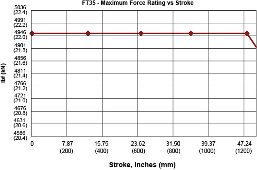
| Maximum Force^1 | lbf | 5000 | 5000 | 5000 | 5000 | 5000 | 5000 |
| kN | 22.2 | 22.2 | 22.2 | 22.2 | 22.2 | 22.2 | |
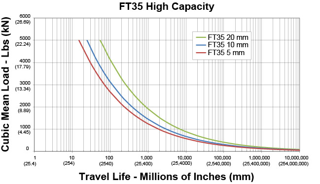
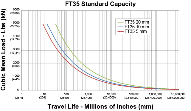
| Estimated L_10 Life at Maximum Force | in x 10^6 | 15.4 | 24.6 | 56.7 | 8.88 | 14.15 | 32.05 |
| km | 392 | 626 | 1440 | 225.6 | 359.4 | 814.2 | |
| C_a (Dynamic Load Rating) | lbf | 21400 | 19850 | 20800 | 17800 | 16500 | 17200 |
| kN | 95.2 | 88.3 | 92.5 | 79.2 | 73.4 | 76.5 | |
| Maximum Input Torque | lbf-in | 196 | 392 | 783 | 196 | 392 | 783 |
| Nm | 22.1 | 44.3 | 88.5 | 22.1 | 44.3 | 88.5 | |
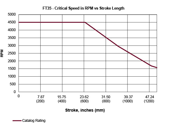
| Max Rated RPM @ Input Shaft | RPM | 4500 | 4500 | 4500 | 4500 | 4500 | 4500 |
| Maximum Linear Speed @ RPM Maximum Rated | in/sec | 14.7 | 29.5 | 59.3 | 14.7 | 29.5 | 59.3 |
| mm/sec | 373 | 750 | 1500 | 373 | 750 | 1500 | |
| 5 MM LEAD | 10 MM LEAD | 20 MM LEAD | ||
|---|---|---|---|---|
| NMT Unit - J (0) | 0.0004087 | 0.0004121 | 0.0004259 | kg-m² (at input shaft) kg-m²/inch of stroke |
| NMT Unit - J (Stroke) | 0.0000159 | 0.0000162 | 0.0000171 | kg-m² (at input shaft) kg-m²/inch of stroke |
| Inline w/ Coupler - J (0) | 0.0005127 | 0.0005161 | 0.0005299 | kg-m² (at motor shaft) kg-m²/inch of stroke |
| Inline w/ Coupler - J (Stroke) | 0.0000159 | 0.0000162 | 0.0000171 | kg-m² (at motor shaft) kg-m²/inch of stroke |
| Parallel 1:1 - J (0) | 0.0011042 | 0.0011855 | 0.001448 | kg-m² (at motor shaft) kg-m²/inch of stroke |
| Parallel 1:1 - J (Stroke) | 0.0000159 | 0.0000162 | 0.0000171 | kg-m² (at motor shaft) kg-m²/inch of stroke |
| Parallel 2:1 - J (0) | 0.0014029 | 0.0014038 | 0.0015345 | kg-m² (at motor shaft) kg-m²/inch of stroke |
| Parallel 2:1 - J (Stroke) | 0.0000040 | 0.0000040 | 0.0000043 | kg-m² (at motor shaft) kg-m²/inch of stroke |
| Standard Inline Coupling Inertia | 0.000104 kg-m² (0.000920 lbf-in s²) | |||
| BASE ACTUATOR WEIGHT | LB | KG |
|---|---|---|
| 6 Inch Stroke Length | 30 | 14 |
| 12 Inch Stroke Length | 35 | 16 |
| 18 Inch Stroke Length | 40 | 18 |
| 24 Inch Stroke Length | 45 | 21 |
| 36 Inch Stroke Length | 55 | 25 |
| 48 Inch Stroke Length | 65 | 30 |
| Adder for Inline (excluding motor) | 8 | 3.6 |
| Adder for Parallel Drive (excluding motor) | 16 | 7.3 |
| Adder for Front Flange | 5.4 | 2.5 |
| Adder for Rear Flange | 7.4 | 3.4 |
| Adder for Rear Clevis | 3 | 1.4 |
| Adder for Rear Eye | NA | NA |
| Adder for Front/Rear Angle Mounts | NA | NA |
| Adder for Two Trunnions | 19.5 | 8.9 |
| Adder for Two Foot Mounts | 3.3 | 1.5 |
Printable view
| HIGH CAPACITY | STANDARD CAPACITY | ||||
|---|---|---|---|---|---|
| 5 | 10 | 5 | 10 | ||
| Screw Lead | in | 0.197 | 0.394 | 0.197 | 0.394 |
| mm | 5 | 10 | 5 | 10 | |
| Maximum Force* | lbf | 10000 | 10000 | 10000 | 10000 |
| kN | 44.5 | 44.5 | 44.5 | 44.5 | |
| Estimated L_10 Life at Maximum Force | in x 10^6 | 9.81 | 19.14 | 5.67 | 11.06 |
| km | 249.2 | 486.3 | 144 | 280.9 | |
| C_a (Dynamic Load Rating) | lbf | 36800 | 36500 | 30650 | 30400 |
| kN | 163.7 | 162.4 | 136.3 | 135.2 | |
| Maximum Input Torque | lbf-in | 392 | 783 | 392 | 783 |
| Nm | 44.1 | 88.2 | 44.1 | 88.2 | |
| Max Rated RPM @ Input Shaft | RPM | 3500 | 3500 | 3500 | 3500 |
| Maximum Linear Speed @ Maximum Rated RPM | in/sec | 11.5 | 23 | 11.5 | 23 |
| mm/sec | 292 | 583 | 292 | 583 | |
*Maximum allowable actuator-generated force that can be applied routinely. Exceeding this force may result in permanent damage to the actuator. For high force, short stroke applications, consult factory.
| 5 MM LEAD | 10 MM LEAD | ||
|---|---|---|---|
| NMT Unit - J (0) | 0.002463 | 0.002474 | kg-m² (at input shaft) kg-m²/inch of stroke |
| NMT Unit - J (Stroke) | 0.000045 | 0.000046 | kg-m² (at input shaft) kg-m²/inch of stroke |
| Inline w/ Coupler - J (0) | 0.002571 | 0.002581 | kg-m² (at motor shaft) kg-m²/inch of stroke |
| Inline w/ Coupler - J (Stroke) | 0.000045 | 0.000046 | kg-m² (at motor shaft) kg-m²/inch of stroke |
| Parallel 1:1 - J (0) | 0.006911 | 0.006921 | kg-m² (at motor shaft) kg-m²/inch of stroke |
| Parallel 1:1 - J (Stroke) | 0.000045 | 0.000046 | kg-m² (at motor shaft) kg-m²/inch of stroke |
| Parallel 2:1 - J (0) | 0.003466 | 0.003469 | kg-m² (at motor shaft) kg-m²/inch of stroke |
| Parallel 2:1 - J (Stroke) | 0.000011 | 0.000011 | kg-m² (at motor shaft) kg-m²/inch of stroke |
| Standard Inline Coupling Inertia | 0.00010743 kg-m² (0.000951 lbf-in s²) | ||
*Pulleys for parallel mount match actuator max performance ratings. Pulley inertias reflected at motor including typical pulleys, belt and standard bushings. Because of differences in belt and pulley selection due to particular motor choices, please contact your local sales representative if these values are critical to your application.
| BASE ACTUATOR WEIGHT | LB | KG |
|---|---|---|
| 6 Inch Stroke Length | 57 | 26 |
| 12 Inch Stroke Length | 68 | 31 |
| 18 Inch Stroke Length | 79 | 36 |
| 24 Inch Stroke Length | 90 | 41 |
| 36 Inch Stroke Length | 112 | 51 |
| 48 Inch Stroke Length | 135 | 61 |
| Adder for Inline (excluding motor) | 7.1 | 3.2 |
| Adder for Parallel Drive (excluding motor) | 42.5 | 19.3 |
| Adder for Front Flange | 6.1 | 2.8 |
| Adder for Rear Flange | 17.4 | 7.9 |
| Adder for Rear Clevis | 18.9 | 8.6 |
| Adder for Rear Eye | 19.8 | 9 |
| Adder for Front/Rear Angle Mounts | NA | NA |
| Adder for Two Trunnions | 17.2 | 7.8 |
| Adder for Two Foot Mounts | 10.4 | 4.7 |
Printable view
| HIGH CAPACITY | STANDARD CAPACITY | ||||||
|---|---|---|---|---|---|---|---|
| 6 | 12 | 30 | 6 | 12 | 30 | ||
| Screw Lead | in | 0.236 | 0.472 | 1.181 | 0.236 | 0.472 | 1.181 |
| mm | 6 | 12 | 30 | 6 | 12 | 30 | |
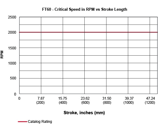
| Maximum Force ^1 | lbf | 20000 | 20000 | 20000 | 20000 | 20000 | 20000 |
| kN | 89 | 89 | 89 | 89 | 89 | 89 | |
| Estimated L_10 Life at Maximum Force | in x 10^6 | 5.7 | 7.3 | 38.6 | 4.1 | 5.2 | 10.7 |
| km | 145.8 | 184.7 | 981.1 | 104.8 | 133.1 | 271.9 | |
| C_a (Dynamic Load Rating) | lbf | 57933 | 49750 | 63958 | 51900 | 44600 | 41700 |
| kN | 257.7 | 221.3 | 284.5 | 230.9 | 198.4 | 185.5 | |
| Maximum Input Torque | lbf-in | 940 | 1880 | 4699 | 940 | 1880 | 4699 |
| Nm | 106 | 212 | 531 | 106 | 212 | 531 | |
| Max Rated RPM @ Input Shaft | RPM | 2000 | 2000 | 2000 | 2000 | 2000 | 2000 |
| Maximum Linear Speed @ Maximum Rated RPM | in/sec | 7.9 | 15.8 | 39 | 7.9 | 15.8 | 39 |
| mm/sec | 201 | 401 | 1000 | 201 | 401 | 1000 | |
1 -Maximum allowable actuator-generated force that can be applied routinely. Exceeding this force may result in permanent damage to the actuator. For high force, short stroke applications, consult factory.
| 6 MM LEAD | 12 MM LEAD | 30 MM LEAD | ||
|---|---|---|---|---|
| NMT Unit - J (0) | 0.0078464 | 0.0078709 | 0.0080424 | kg-m² (at input shaft) kg-m²/inch of stroke |
| NMT Unit - J (Stroke) | 0.0002539 | 0.0002547 | 0.00026 | kg-m² (at input shaft) kg-m²/inch of stroke |
| Inline w/ Coupler - J (0) | 0.0081764 | 0.0082009 | 0.0083724 | kg-m² (at motor shaft) kg-m²/inch of stroke |
| Inline w/ Coupler - J (Stroke) | 0.0002539 | 0.0002547 | 0.00026 | kg-m² (at motor shaft) kg-m²/inch of stroke |
| Parallel 1:1 - J (0) | 0.0129357 | 0.0146113 | 0.0312682 | kg-m² (at motor shaft) kg-m²/inch of stroke |
| Parallel 1:1 - J (Stroke) | 0.0002539 | 0.0002547 | 0.00026 | kg-m² (at motor shaft) kg-m²/inch of stroke |
| Parallel 2:1 - J (0) | 0.0049158 | 0.0057202 | 0.0214777 | kg-m² (at motor shaft) kg-m²/inch of stroke |
| Parallel 2:1 - J (Stroke) | 0.0000635 | 0.0000637 | 0.0000650 | kg-m² (at motor shaft) kg-m²/inch of stroke |
| Standard Inline Coupling Inertia | 0.000330 kg-m² (0.002921 lbf-in s²) | |||
*Pulleys for parallel mount match actuator max performance ratings. Pulley inertias reflected at motor including typical pulleys, belt and standard bushings. Because of differences in belt and pulley selection due to particular motor choices, please contact your local sales representative if these values are critical to your application.
| BASE ACTUATOR WEIGHT | LB | KG |
|---|---|---|
| 12 inch Stroke Length | 100 | 45 |
| 24 inch Stroke Length | 130 | 59 |
| 36 Inch Stroke Length | 160 | 72 |
| 48 Inch Stroke Length | 190 | 86 |
| Adder for Inline (excluding motor) | 20.4 | 9.3 |
| Adder for Parallel Drive (excluding motor) | 39.1 | 17.7 |
| Adder for Front Flange | 13.4 | 6.1 |
| Adder for Rear Flange | 15.9 | 7.2 |
| Adder for Rear Clevis | 11.1 | 5 |
| Adder for Rear Eye | NA | NA |
| Adder for Front/Rear Angle Mounts | NA | NA |
| Adder for Two Trunnions | 44.3 | 20.1 |
| Adder for Two Foot Mounts | 10.4 | 4.7 |
Printable view
| HIGH CAPACITY | STANDARD CAPACITY | ||||||
|---|---|---|---|---|---|---|---|
| 6 | 12 | 30 | 6 | 12 | 30 | ||
| Screw Lead | in | 0.236 | 0.472 | 1.181 | 0.236 | 0.472 | 1.181 |
| mm | 6 | 12 | 30 | 6 | 12 | 30 | |
| Maximum Force^1 | lbf | 40000 | 40000 | 40000 | 40000 | 40000 | 40000 |
| kN | 177.9 | 177.9 | 177.9 | 177.9 | 177.9 | 177.9 | |
| Estimated L_10 Life at Maximum Force | in x 10^6 | 3.1 | 4.4 | 16.3 | 1.94 | 2.55 | 5 |
| km | 78.7 | 111.4 | 414.3 | 49.3 | 64.9 | 127 | |
| C_a (Dynamic Load Rating) | lbf | 94330 | 84079 | 95971 | 80700 | 70200 | 64700 |
| kN | 419.6 | 374 | 426.9 | 359 | 312.2 | 287.8 | |
| Maximum Input Torque | lbf-in | 1880 | 3760 | 9399 | 1880 | 3760 | 9399 |
| Nm | 212 | 425 | 1062 | 212 | 425 | 1062 | |
| Max Rated RPM @ Input Shaft | RPM | 1750 | 1750 | 1750 | 1750 | 1750 | 1750 |
| Maximum Linear Speed @ Maximum Rated RPM | in/sec | 6.9 | 13.8 | 34.4 | 6.9 | 13.8 | 34.4 |
| mm/sec | 175 | 351 | 875 | 175 | 351 | 875 | |
1- Maximum allowable actuator-generated force that can be applied routinely. Exceeding this force may result in permanent damage to the actuator. For high force, short stroke applications, consult factory.
| 6 MM LEAD | 12 MM LEAD | 30 MM LEAD | ||
|---|---|---|---|---|
| NMT Unit - J (0) | 0.0302504 | 0.0303275 | 0.0308673 | kg-m² (at input shaft) kg-m²/inch of stroke |
| NMT Unit - J (Stroke) | 0.0008022 | 0.0008035 | 0.0008124 | kg-m² (at input shaft) kg-m²/inch of stroke |
| Inline w/ Coupler - J (0) | 0.0314604 | 0.0315375 | 0.0320773 | kg-m² (at motor shaft) kg-m²/inch of stroke |
| Inline w/ Coupler - J (Stroke) | 0.0008022 | 0.0008035 | 0.0008124 | kg-m² (at motor shaft) kg-m²/inch of stroke |
| Parallel 1:1 - J (0) | 0.0721056 | 0.0535533 | 0.1342578 | kg-m² (at motor shaft) kg-m²/inch of stroke |
| Parallel 1:1 - J (Stroke) | 0.0008022 | 0.0008035 | 0.0008124 | kg-m² (at motor shaft) kg-m²/inch of stroke |
| Parallel 2:1 - J (0) | 0.0198765 | 0.027049 | 0.0753395 | kg-m² (at motor shaft) kg-m²/inch of stroke |
| Parallel 2:1 - J (Stroke) | 0.0002006 | 0.0002009 | 0.0002031 | kg-m² (at motor shaft) kg-m²/inch of stroke |
| Standard Inline Coupling Inertia | 0.0001210 kg-m² (0.010709 lbf-in s²) | |||
*Pulleys for parallel mount match actuator max performance ratings. Pulley inertias reflected at motor including typical pulleys, belt and standard bushings. Because of differences in belt and pulley selection due to particular motor choices, please contact your local sales representative if these values are critical to your application.
| BASE ACTUATOR WEIGHT | LB | KG |
|---|---|---|
| 12 Inch Stroke Length | 190 | 86 |
| 24 Inch Stroke Length | 265 | 120 |
| 36 Inch Stroke Length | 340 | 153 |
| 48 Inch Stroke Length | 415 | 187 |
| Adder for Inline (excluding motor) | 54.9 | 24.9 |
| Adder for Parallel Drive (excluding motor) | 79.1 | 35.9 |
| Adder for Front Flange | 28.5 | 17.5 |
| Adder for Rear Flange | NA | NA |
| Adder for Rear Clevis | NA | NA |
| Adder for Rear Eye | NA | NA |
| Adder for Front/Rear Angle Mounts | NA | NA |
| Adder for Two Trunnions | NA | NA |
| Adder for Two Foot Mounts | 34.8 | 15.8 |
Printable view
Catalogs, Brochures, and Success Stories
Manuals and Technical Tips
Find more resources in our InfoCenter.
Please log in or register to use our model configurator, with this you can view and download 3D and 2D models and drawings, as well as build and submit a quote request.
If you do not have a login, please proceed to the registration page
If you currently have an Exlar website account and would like to delete it, please contact [email protected]